About Me CV Research GitHub Google Scholar
Quadcopter
Why?
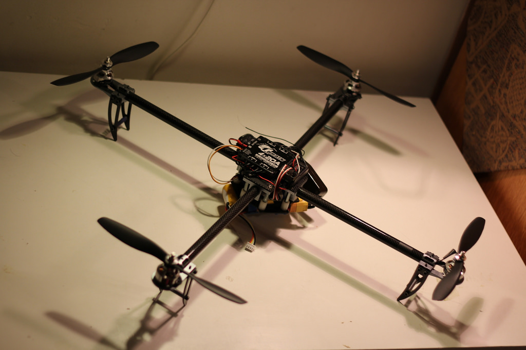
The quadcopter is a project I started with friends after the robot arm just before entering college. Interested in the versatility and acrobatics of the seemingly simple UAV I built one from scratch to fully understand it.
Microcontroller and Sensors
The quad is powered by a Teensy 3.1 ARM microcontroller coded in Arduino and an IMU that are stored within the central piece. The Teensy communicates with the IMU via I2C.
Really Compact!
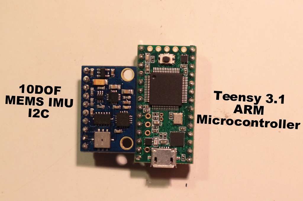
On the left is the 10-degrees-of-freedom Inertial Measurement Unit. It consists of a triple-axis accelerometer, gyroscope, and magnetometer, along with a barometer for altitude control (for a total of 10 DOF). On the right is the ultra-fast ARM processor!
Data and Power Supply
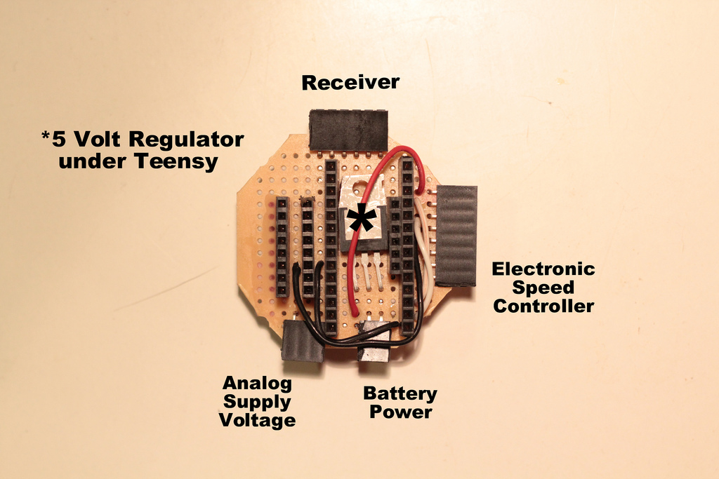
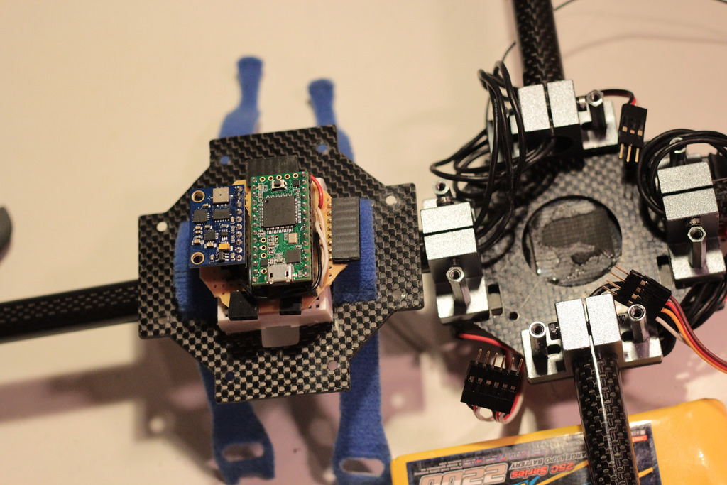
I soldered together a small PCB to hold the MEMS sensors and microcontroller in place. An intermediate voltage regulator steps down the battery voltage so it can then be handled by the weaker regulator on the Teensy.
Detachable, Debuggable
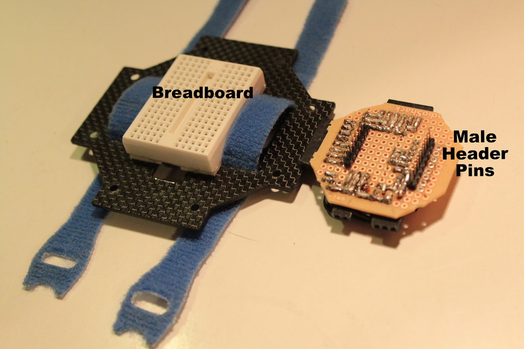
Male header pins soldered to the board's underside let it attach to a mini breadboard within the quadcopter. So not only are each of the chips removable, but the entire setup can be taken out and tested for debugging.
Electronic Speed Controller (ESC)
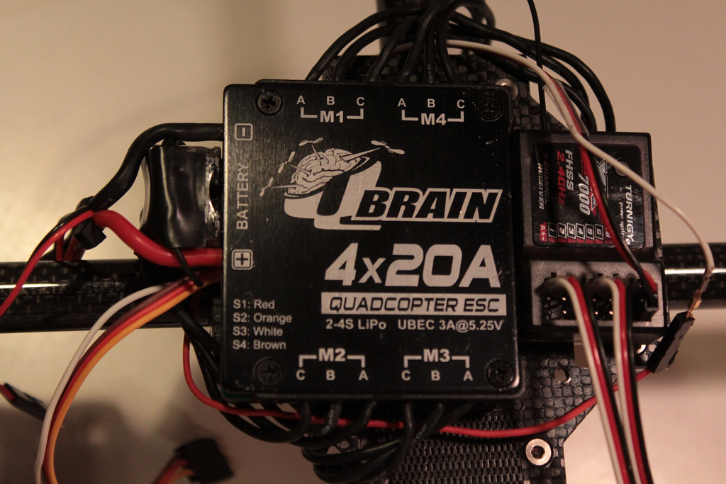
Each motor's speed is controlled by a Q Brain quadruple ESC using PWM outputs from the microcontroller. Rotational direction cannot be changed without rewiring the motors.
Transmission Reading via ISRs
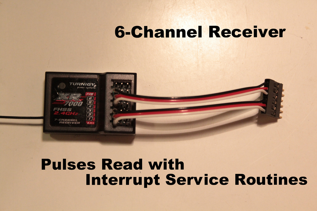
The quadcopter receives input from a 2.4 GHz RF 6 channel receiver, which in turn receives input from the pilot's handheld transmitter. It works by sending surprisingly infrequent pulses to the microcontroller, requiring interrupt service routines to monitor the transmitter's activity without having to slow down the processor.
Sensor Fusion
To calculate the tilt of the quadcopter along each axis (pitch/roll/yaw), it fuses the data from all three triple-axis sensors.
Why use them all? Integrating the values from the gyroscope alone with respect to time passed from an initial condition (rotational VELOCITY to tilt ANGLE) produces drift in the long run due to the inherent slow sampling rate of the sensor. Using the accelerometer alone to find the force of gravity (an absolute, downward direction), to find the current, absolute tilt angles is inefficient unless the quad is at constant velocity 100% of the time. The triple-axis magnetometer is for getting an absolute heading (determined by the earth's poles); however even this 3-dimensional data would be skewed without considering tilt, since heading is one dimensional.
To overcome this problem, the quadcopter implements a low pass filter for the gyroscope and a high pass filter for the accelerometer. Once these two values are then fused into a single tilt value (for each axis), the magnetometer readings can then be corrected to produce the true 2-dimensional heading.
PID Looping

Once the tilt values are calculated, the quadcopter compares them to the desired tilt values, which is set by the transmitter. The amount of error between these two values are constantly fed into the correct PID loop to dispense the appropriate amount of power to be sent to each motor. There are three PID loops for each tilt axis (roll/pitch/yaw) and another PID loop for altitude hold.